
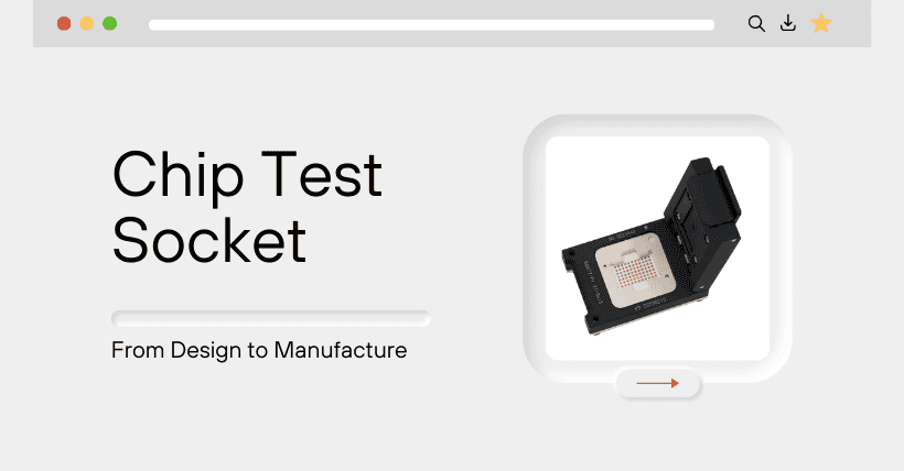
1. What is A Chip Test Socket?
A chip test socket is a specialized fixture used in the semiconductor testing process. It allows chips to be mounted on testing equipment without soldering, enabling various electrical and functional tests. Test sockets play a critical role in the production and development of integrated circuits (ICs), particularly in wafer-level testing (CP testing) and post-packaging testing.
2. Functions and Features of Chip Test Sockets
■ Reusable
Test sockets are designed to be used multiple times, allowing for repeated use in different testing processes without damaging the chip.
■ Easy to Install and Remove
Test sockets allow for quick installation and removal of chips, simplifying the testing process and improving testing efficiency.
■ Reliable Electrical Connection
Test sockets provide stable electrical connections, ensuring reliable signal transmission between the chip and the testing equipment, and accurate test results.
■ Thermal Management
Some test sockets are designed with heat dissipation features, effectively managing the chip’s temperature during testing to prevent overheating.
3. Before Socket Design, the Following Information is Required
Prior to socket design, it is essential to clarify the testing requirements that the socket needs to fulfill. This is crucial for communication between chip developers and socket engineers. Generally, the following details need to be determined:
■ Type of Chip Testing
This includes whether it is a burn-in test socket, finished product test socket, programming socket, ESD socket, etc., as well as the specific testing scenario.
■ Provide the Chip’s POD (Package Outline Drawing)
The POD describes the specific dimensions and shape of the chip package. It includes detailed information on the package type, the number of chip pins, chip dimensions, and pin pitch.
■ Chip Testing Parameter Requirements
This includes the chip power, maximum current per pin, highest frequency per pin, chip junction temperature, thermal resistance, insertion loss, and return loss for RF chips, among other parameters.
4. Socket Design
Based on the chip testing requirements, the socket is designed in detail, including the following main aspects:
■ Determining the Socket Structure
Socket structures mainly include single-latch flip-top, double-latch, lever, and knob types.
■ Selecting the Shell Processing Type
Shells can be classified into two types based on the processing method: injection-molded shells and machined shells.
Injection-molded shells are mass-produced using engineering plastics and are relatively low-cost.
Machined shells are made from metals (usually aluminum alloy) or engineering plastics (such as PEEK, Torlon, etc.) using CNC machining, and are relatively high-cost, mainly used in high-performance custom sockets.
■ Selecting the Pogo Pin
Factors influencing the selection of Pogo Pins include chip pitch, maximum current per pin, highest frequency per pin, and chip package type.
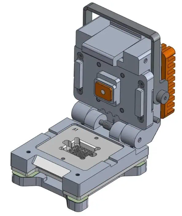
■ Conducting the 3D Design of the Socket Structure
The mechanical structure of the socket mainly consists of the lower pin plate, upper pin plate, floating plate, limit frame, pressure block, and shell (including the base and cover, with some designs integrating the base function into the pin plates).
Pogo Pins are placed in the cavity formed between the lower pin plate and the upper pin plate. All three-dimensional parts are assembled to form the socket’s overall 3D assembly drawing.
■ Drawing Mechanical Engineering Diagrams of the Socket and Its Parts
Mechanical engineering diagrams will include a set of part views, all dimensions, tolerances, and technical requirements. These serve as the basis for part preparation, processing, manufacturing, quality inspection, and measurement.
5. Adjusting Socket Details Based on Simulation Results
Simulation involves using models in a computer system to “reproduce” the activities of a real system. By comparing the simulation results with the design expectations, the design model is adjusted to ensure that the simulation results meet the design requirements.
Simulations for sockets mainly involve signal simulation and thermal simulation.
■ Socket Signal Simulation
Based on customer needs, electrical signal simulation is performed on a specific area in the PIN MAP, usually a 3X3 or 5X5 area. Through 3D modeling simulation, the overall performance of this part, such as insertion loss, return loss, and parasitic parameters, is obtained.
Customers can confirm whether the socket’s performance meets their expectations, minimizing PI/SI issues caused by the socket in actual use.
■ Socket Thermal Simulation
This involves overall thermal simulation of the socket, IC, and PCB. By establishing an integrated thermal simulation model of the socket, chip, and PCB, and considering environmental factors like wind speed, wind direction, and heat sources, the thermal distribution in the actual testing environment of the chip is accurately reflected. The differences between this and the expected targets are analyzed to guide the optimization design of the socket’s thermal model, including optimizing the material, structure, and size of the socket’s thermal module.
6. Mechanical Processing of Socket Parts
After optimizing the design through simulation iterations and meeting design requirements, a complete socket model and drawings will be generated and sent to the factory for production using CNC (Computer Numerical Control) machines.
The processing and production of parts mainly include two stages: CNC programming and CNC operation.
■ CNC Programming
This is the process of using a computer to generate machining programs for CNC machines. It involves developing the CNC machining plan and processes according to the design and technical requirements of the part drawings. This includes determining the machining sequence, selecting tools, and setting cutting parameters.
The CNC program consists of a series of instructions that control the movement of the CNC machine’s cutting tools, removing excess material from the raw piece to produce parts that meet the dimensions and tolerance requirements specified in the drawings.
■ CNC Operation
This is the actual process of machining and shaping parts on a CNC machine using the completed CNC program. Adjusting the machine according to the CNC program is a crucial step in the production of each part, essentially preparing for successful part production. For subsequent production of the same parts, this adjustment process can be skipped.
Therefore, the processing costs for batch parts and small quantities of single parts primarily depend on the distribution of the setup costs. The processing cost for small quantities of single parts is significantly higher than that for large batches.
7. Assembling Parts into Finished Sockets
■ In the assembly department, assembly workers follow standard assembly procedures and use the socket assembly diagram to assemble qualified socket parts and purchased components into finished sockets.
■ Due to the small and precise dimensions of parts such as pogo pins and pin plates, assembly often requires the use of tools like microscopes for assistance.
Additionally, specialized fixtures are designed and manufactured to ensure consistency and improve efficiency during the assembly process.
8. Process Inspection and Quality Control
To ensure the quality of socket products, quality control must be implemented throughout the entire production process. This includes three main areas: incoming material quality control, in-process quality control, and finished product quality control.
■ Incoming Material Quality Control
For socket products, the core purchased components and raw materials mainly include pogo pins and engineering plastics. General raw materials and purchased parts include aluminum alloy, copper metals, and hardware (springs, screws, nuts, etc.).
■ In-Process Quality Control
During parts processing and product assembly, initial inspection and patrol inspection must be arranged and implemented, with appropriate records and reports maintained.
■ Finished Product Quality Control
Before shipment, socket products must undergo quality inspections, which primarily include: appearance inspection, key dimensions and tolerance checks, and functional movement tests. Based on these inspections, a final product inspection report is completed, which serves as an attachment for the shipment of socket products.
Related:

Disclaimer: This article is created by the original author. The content of the article represents their personal opinions. Our reposting is for sharing and discussion purposes only and does not imply our endorsement or agreement. If you have any objections, please get in touch with us through the provided channels.